Hello, if you have any need, please feel free to consult us, this is my wechat: wx91due
CS3388B Assignment 6
General Instructions: This assignment consists of 7 pages, 1 exercise, and is marked out of 100. For any question involving calculations you must provide your workings. Correct final answers without workings will be marked as incorrect. Each assignment submission and the answers within are to be solely your individual work and completed independently. Any plagiarism found will be taken seriously and may result in a mark of 0 on this assignment, removal from the course, or more serious consequences.
Submission Instructions: The answers to this assignment (code, workings, written answers) are to be submitted electronically to OWL. Ideally, any workings or written answers are to be typed. At the very least, clearly scanned copies (no photographs) of hand-written work. If the person correcting your assignment is unable to easily read or interpret your written answers then it may be marked as incorrect without the possibility of remarking. Include a README with any code.
Install Tips: I highly recommend downloading GLEW: https://glew.sourceforge.net/and (if working in C++) GLM: https://www.opengl.org/sdk/libs/GLM/. My example code (which you should pillage to help do this assignment) use GLEW and GLM.
Exercise 1. The goal of this assignment to generate a basic water shader that uses tesselation, geometry shaders, and displacement maps.
At a high-level, your program will:
• Take a simple mesh of triangles as input.
• Tesselate that mesh to get more vertices to play with in the geometry shader.
• Manipulate the mesh in the geometry shader to create waves.
• Add some other texture/depth to the generated waves to make it look good.
The end product of this assignment is to have a program which just renders a patch of water.
The Camera.
1. Two options, so it must fit one of two paradigms. A “third person” camera, which allows movement within the world across the top of the water, or a “globe” movement similar to assignment 5.
The Vertex Specification.
1. In the appendix there is simple code to generate a mesh of quads which range over [min, max] in both x and z to create a flat plane. In this mesh, each quad is of size stepsize.
2. You can use this code, or something of your own making, to generate the mesh.
The Vertex Shader.
1. Your vertex shader should simply output vertex positions in world coordinates. Do not yet multiply by MVP.
2. Use uniforms in your vertex shader to compute things like light and eye direction for later use in the Phong-like fragment shader.
3. Your VS should also output UV coordinates which change over time. As you will see, the movement of waves in the geometry shader should be somehow reflected in the movement of UV coordinates for the rendered texture. Something like:
1 vec2 uv = (Position_worldspace.xz + texOffset + (time*0.08))/texScale;
The Tesselation.
1. Use a Tesselation Control Shader and a Tesselation Evaluation Shader to tesselate your quad mesh into a finer grid. Do not simply use a smaller step size for the creation of the mesh.
2. Use quads as the abstract patch type.
3. Use at least 16 as the level of inner and outer tesselation.
4. Your TES should compute (interpolate) values needed for the eventual geometry shader. This includes vertex world position and uv coordinates,
5. Your TES should compute (interpolate) values needed for the eventual fragment shader. This includes light direction and eye direction.
The Geometry Shader.
This represents the bulk of the work for this assignment. The geometry shader should receive many vertices (grouped into triangles) from the tesselation shaders. Then, the geometry shader should manipulate the vertices in the plane as to create waves.
In particular, Gerstner waves.
An excellent explanation can be found at:https://developer.nvidia.com/gpugems/gpugems/part-i-natural-effects/chapter-1-effective-water-simulation-physical-models
Gerstner waves have a relatively simple formula which leads to very complex results. The idea is to specify one wave at a time and then add them all together (i.e. superposition).
• wi is the wave frequency. The larger it is, the more ups and downs in your wave.
• Di is the overall transverse movement direction of the wave (in two dimensions).
• Ai is the amplitude of the wave.
• φi is the phase shift of the wave.
• Qi is a measure of the “sharpness” of the wave’s peak.
For the ith wave travelling along the y = 0 plane, the initial position (x0,0,z0) is perturbed over time t as:
x = QiAiDix cos(wiDi . (x0,z0) + φt)
y = Ai sin(wiDi . (x,z) + φt)
z = QiAiDiz cos(wiDi . (x0,z0) + φt)
where Dix is the x-component of the 2D movement vector Di; similarly for Diy.
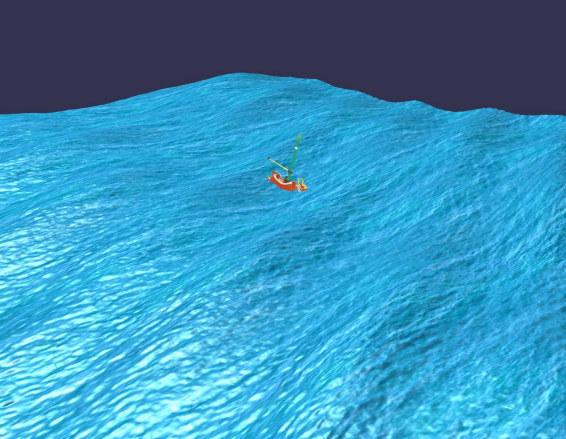
Given a point (x,0,z) on the tessellated quad plane (in world coordinates) we can use a geometry shader to add the influence of multiple waves over time.![]()
vec3 Gerstner(vec3 worldpos, float w, float A, float phi, float Q, vec2 D, int N);
void main() { ...
//The wave functions used in the above screenshot.
for(int i = 0; i < gl_in.length(); ++i) { pos[i] = vec4(position_tes[i], 1.0);
pos[i] += vec4(Gerstner(position_tes[i],
4, 0.08, 1.1, 0.75, vec2(0.3, 0.6), 4), 0.0); pos[i] += vec4(Gerstner(position_tes[i],
2, 0.05, 1.1, 0.75, vec2(0.2, .866), 4), 0.0); pos[i] += vec4(Gerstner(position_tes[i],
0.6, 0.2, 0.4, 0.1, vec2(0.3, 0.7), 4), 0.0); pos[i] += vec4(Gerstner(position_tes[i],
0.9, 0.15, 0.4, 0.1, vec2(0.8, 0.1), 4), 0.0); }
...
gl_Position = MVP * pos[i];
...
EmitVertex(); ...
}
Because of the way superposition works when we add those waves together, the Qi for “sharpness” of a wave has extra constraints. This is given by N in the Gerstner function. Each Gerstner wave receives a Q value between 0 and 1. The closer to 1, the more sharp the wave.
Then, each wave’s actual Qi value is computed as w iAQiN , were N is the total number of waves to combine.
Notice that the geometry shader computes everything in world coordinates and then finally multiplies by the MVP uniform to output vertex positions in clip coordinates.
In total, your geometry shader should perform the following.
1. Use a displacement map to add extra depth to the y value of pos[i]. (See Lecture 17).
2. Combine together at least two different waves to change the position of each vertex in the mesh over time. The positions of the vertices must move over time using an input uniform time.
3. After perturbating the vertices by the waves, re-calculate the normal for the triangle currently being processed by the geometry shader. You should do this manually using cross products. This is needed to get correct reflection in the Fragment Shader.
4. The GS should output any values needed by the Phong-like fragment shader: eye direction, light direction, normal, etc.
The Fragment Shader.
1. Implement a Phong-like reflection model which includes ambient, diffuse, and specular components.
2. Your base diffuse color should come from a texture. For example, see the water.bmp texture supplied with this assignment. Although, you can use any texture you want.
Notes:
• Your shader program will require at least two textures at once. One for the displacement map and another for the water texture to be used in the fragment shader. Make sure you set the values of the sample2D uniforms properly to match the GL_TEXTUREi
• A lot of boilerplate code is supplied in the .zip attached to this.
• See a video of the waves moving under resources on OWL.
The Submission.
Submit to OWL:
1. Your source code. (One or more files depending on how you defined the classes).
2. A README explaining what you did and why you did it like that, any known bugs, instructions for compiling. It doesn’t have to be long, but it should be informative to the person marking.
3. A screenshot of your waves.
void planeMeshQuads(float min, float max, float stepsize) {
// The following coordinate system works as if (min, 0, min) is the origin
// And then builds up the mesh from that origin down (in z)
// and then to the right (in x). fixed x and increasing
// So, one "row" of the mesh’s vertices have a z
//manually create a first column of vertices float x = min; float y = 0; for
(float z = min; z <= max; z += stepsize) {
verts.push_back(x);
verts.push_back(y);
verts.push_back(z);
normals.push_back(0);
normals.push_back(1);
normals.push_back(0);
}
for (float x = min+stepsize; x <= max; x += stepsize) {
for (float z = min; z <= max; z += stepsize) {
verts.push_back(x);
verts.push_back(y); verts.push_back(z);
normals.push_back(0);
normals.push_back(1);
normals.push_back(0); }
}
int nCols = (max-min)/stepsize + 1; int i = 0, j = 0; for (float x = min; x < max;
x += stepsize) { j = 0; for (float z = min; z < max; z += stepsize) {
indices.push_back(i*nCols + j); indices.push_back(i*nCols + j + 1);
indices.push_back((i+1)*nCols + j + 1); indices.push_back((i+1)*nCols + j);
++j;
}
++i;
}
}