Hello, if you have any need, please feel free to consult us, this is my wechat: wx91due
ELEC9713
Industrial and Commercial Power Systems
Tutorial 1
1. The electrical installation of an industrial site is supplied by three-phase 415V with the following loads:
100 60W lighting points
20 50W exhaust fans (permanently connected)
80 10A 1-phase single socket outlets
10 15A 1-phase socket outlets
1 5.5kW/10A 3-phase rolling machine motor
2 4kW/8A 3-phase lathe motors
1 4.8kW 1-phase storage water heater
Refer to the appropriate Australian Standard(s):
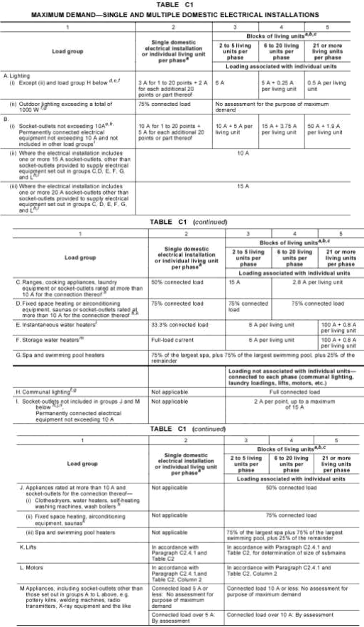
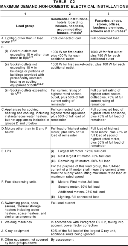
(i) Specify the load group for each type of load listed above.
(ii) Describe one arrangement for load connection across the three-phase supply. It is required to spread the load evenly among the three phases.
(iii) Determine the maximum demand of the heaviest loaded phase.
2. The supply to a building is fed directly from a 11kV/415V/1MVA substation transformer that belongs to the electricity distributor. The transformer impedance is a typical value of 5%. Calculate:
(i) The full-load current rating of the transformer.
(ii) The effective transformer impedance under short-circuit conditions.
(iii) The prospective short-circuit current and indicate any assumptions made.
(iv) If the transformer impedance is 6.5%, recalculate the prospective short-circuit current.
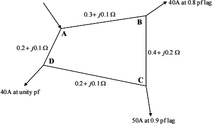
3. Determine the current distribution in the ring main three-phase system (shown in the figure
below), fed at A, with the specified loads and line impedances. The loads are balanced.
Determine the load with the lowest voltage and evaluate the drop between it and A.
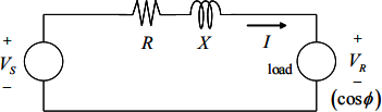
4. For the circuit shown below, it may be assumed that the circuit is one phase of a balanced 3-phase distribution system. The total load is 20 kW at 0.9 leading power factor (at the load). The source end voltage VS is 424 volts and the total line impedance per phase is (0.5+j0.7) ohms. Determine the voltage at the load. Hence determine the line voltage drop. Is the line drop within the limits of ±6% ? Do the calculation using:
(a) an accurate method to determine the full voltage phasor
(b) an approximate method to get the load voltage magnitude only.
5. The approximate equation ΔV = IRcosφ+ IX sinφ can be used to calculate the regulation of a transformer when supplying a load which is operating at a power factor of cosφ , where φ is positive for lagging power factor and negative for leading power factor. Using the above equation, determine the conditions, in terms of the relation of φ to R and X, which will give:
(a) maximum voltage drop (regulation) in the transformer at a fixed load current level
(b) zero voltage drop (regulation) in the transformer
Neglect any other impedance between the source and the load.
In case (b), you should find that the required conditions correspond to a leading power factor at the load. Plot a detailed graph showing how the transformer voltage drop varies with the leading power factor value.
6. Show that the approximate voltage drop equation:

for the drop in an impedance Z = R + jX between a source and a load can also be written as:
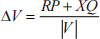
where |V |is the load voltage magnitude and P is the load real power in watts and Q is the load reactive power in VARs.
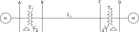
7. The single-line diagram of an unloaded three-phase power system is shown below. The component ratings are as follows.
Generator G1: 20MVA, 13.8kV, X=0.2pu
Generator G2: 30MVA, 18kV, X=0.2pu
Transformer T1: 25MVA, 220Y/13.8Δ kV, X=10%
Transformer T2: 30MVA, 220Y/18 Δ kV, X=10%
Line L1: j80Ω per phase.
Draw the per unit impedance diagram using 50MVA, 13.8kV bases in the circuit of generator G1. Clearly mark all impedance values on the diagram.
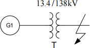
8. A 3-phase synchronous generator is rated 50MVA, 13.2kV, 0.8pf lagging, and has a synchronous reactance of 20%. The generator is connected to a 60MVA, 13.4/138kV, 3-phase transformer having a reactance of 15%. The generator is initially operating on no load and at rated terminal voltage. A bolted 3-phase symmetrical fault occurs on the high-voltage terminals of the transformer. Determine the short-circuit current supplied by the generator and its terminal voltage.
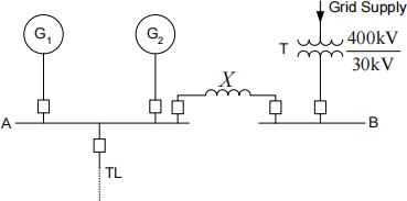
9. Consider the three-phase power system shown below. Generators G1 and G2 are connected in parallel to a 30-kV busbar A. The ratings of G1 and G2 are 100MVA, 30kV, X=20% and 50MVA, 30kV, X=15% respectively. Busbar A feeds a transmission line TL. A grid supply is connected to the station busbar B through a transformer T rated for 500MVA, 400/30kV, X=20%.
Determine the reactance (in ohms) of a current limiting reactor X to be connected between the grid system (busbar B) and the 2-generator busbar (busbar A) such that the short-circuit MVA at bus A does not exceed 1250MVA.
AS/NZS 3000:2007
AS/NZS 3000:2007