Department of Electronic Engineering
Year 2023-24
EE3070 Digital Systems Design
CW Assignment 2: Coursework (Spring term)
Contributes: 70% to final course/module grade
Submission type and Deadlines: A (zipped) compressed electronic copy of the VIVADO project to be uploaded on Moodle by 13:00 (GMT) on Monday, 25th March 2024.
Assessment: The coursework will be assessed through a Moodle test on Monday, 25th March 2024 at 13:00 (GMT) and contributes 70% of this element of assessment. The remaining 30% will be awarded to the VHDL design.
NOTE1: No extensions are permitted.
NOTE2: The Moodle test can betaken only after the submission of the VIVADO project.
Coursework information:
The task
Design, simulate and implement into FPGA an accelerometer-based compass. The system designed will be able to read and display the values set from the board switches or from the accelerometer. The software suite to be used for synthesis, implementation and analysis of the produced VHDL designs is VIVADO 2019.2 targeting the XC7A100T- 1CSG324C device (Nexys-A7 development board).
Assignment content and marks weighting allocation:
Write the necessary VHDL code for designing the compass following the stages described below.
Stage 1: 7segments display converter (60%)
Using the structural design style, write the VHDL code of a digital system that displays the value of the two’scomplement of 12-bit signed binary number on a 7-segment display. For this, the digital system will contain the following components:
a. A component that selects to display the number set using the switches SW11 to SW0 on the Nexys A7 if SW15 is ON. (5%)
b. A component that converts the two’s complement of the 12-bit signed binary number to a signed integer.(10%)
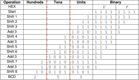
c. A component that converts the integer part into a BCD representation using the algorithm below given for an 8-bit binary number (10%)
o Step 1: Check if any of the Hundreds, Tens and Units columns is greater than 4. If true, add 3 to that column.
o Step 2: Shift all bits to the left 1 position.
o Step 3: If 8 shifts have been performed, the BCD values are given by each column (Hundreds, Tens and Units). Otherwise goto Step 1.

Fig.1 BCD conversion algorithm for an 8-bit binary number
d. A module that converts a one-digit decimal number to 7 segment representation. (5%) e. A module that generates a 250Hz clock signal. (5%)
f. A module to control the anodes of the four seven-segment LEDs separately by activating alternatively each seven-segment digit and write the corresponded BCD value and sign with a frequency of 250 Hz. (10%)
g. The top-level module to include and instantiate all the modules designed above. (5%) h. Create an appropriate test bench and simulate the code. (10%)
Stage 2: Read the accelerometer (40%)
a. Using the VHDL modules provided, write the appropriate code for reading the acceleration values from the ADXL362 sensor when SW 15 is OFF. Display the value of one of the accelerations (there are 3 accelerations read from the sensor) on the 7segment display (10%)
b. Using minimum hardware resources, design in VHDL and implement an 8-point moving average filter module for calculating the average acceleration of the 3 axes over 8 samples. (15%)
c. Light the Nexys A7’s RGB LED in different colours depending on the Nexys A7 board orientation
given by the average X, Y and Z values (orientations to consider are given in Fig.2 below) (15%)

Fig.2 Board orientation vs. X, Y, Z values
For further information on the Departmental policies shown below, please refer to your 2023/24 BEng/MEng Student Handbook in the “ Electronic Engineering Student Information” page on Moodle.
• Coursework requirements (clause 9.9) which includeshow to submit via Moodle Turnitin
• Submission Deadlines (clause 9.9.3) and penalties for late submission (clause 9.9.3)
• Extensions (clause 9.11)
• Academic Misconduct/Assessment Offences (clause 9.6)