Hello, if you have any need, please feel free to consult us, this is my wechat: wx91due
Foundations of Robotics (ROB-GY 6003)
Homework Assignment | Chapter 3
Homework Problems: 3.1, 3.4 (regard {S} as {0}, and {T} as {3}), 3.8, 3.12, 3.16, 3.17
EXAMPLE 3.3
Figure 3.6(a) shows a three-link planar arm. Because all three joints are revolute, this manipulator is sometimes called an RRR (or 3R) mechanism. Fig. 3.6(b) is a schematic representation of the same manipulator. Note the double hash marks
70 Chapter 3 Manipulator kinematics
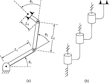
3.1 [15] Compute the kinematics of the planar arm from Example 3.3.
3.4 [22] The arm with three degrees of freedom shown in Fig. 3.30 has joints 1 and 2 perpendicular, and joints 2 and 3 parallel. As pictured, all joints are at their zero location. Note that the positive sense of the joint angle is indicated. Assign link frames (0) through (3) for this arm-that is, sketch the arm, showing the attachment of the frames. Then derive the transformation matrices  ,
,  , and
, and  .
.
3.8 [13] In Fig. 3.31, the location of the tool,  , is not accurately known. Using force control, the robot feels around with the tool tip until it inserts it into the
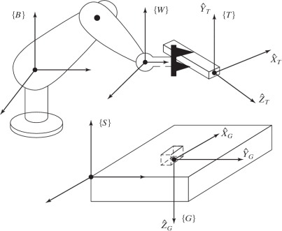
FIGURE 3.31: Determination of the tool frame (Exercise 3.8).
00 Chapter 3 Manipulator Kinematics
socket (or Goal) at location  . Once in this "calibration" configuration (in which (G) and (T) are coincident), the position of the robot,
  , is figured out by reading the joint angle sensors and computing the kinematics. Assuming
  and
and  are known, give the transform equation to compute the unknown tool frame,
  .
.
3.12 [08] Can an arbitrary rigid-body transformation always be expressed with four parameters (a, α, d, θ) in the form of equation (3.6)?
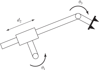
FIGURE 3.36: RPR planar robot (Exercise 3.16).
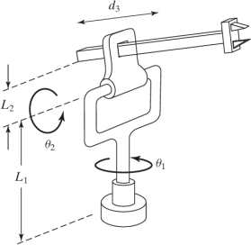
FIGURE 3.37: Three-link RRP manipulator (Exercise 3.17).
3.16 [15] Assign link frames to the RPR planar robot shown in Fig. 3.36, and give the linkage parameters.
3.17 [15] Show the attachment of link frames on the three-link robot shown in Fig. 3.37.